Introduction
Power control is one of the most complicated subject in wireless communication technologies. Today we will try to have an overall idea about LTE Uplink Power Control with understanding each part of the calculation mechanism, but prior to diving to the topic let’s check a bit other things related to the power.
In physics, definition of power is the amount of energy transferred or converted per unit time. The unit of the power is Watt, but it can also be converted to other units such as dBm (Watt is a linear unit, while dBm is a logarithmic unit). Why we mentioned dBm here, because basically in radio telecommunication measurements the dBm or in longer version decibel-milliwatt is also used.
1 watt is equal to 30dBm (1W = 1000mW = 30dBm)
2 watts is equal to 33dBm (2W = 2000mW = 33dBm)
1 milliwatt is equal to 0 dBm (1mW = 0dBm)
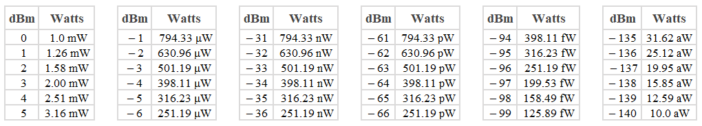
Ok, but in the field when we open our drive test tool and we can see the measured signal level with negative values, e.g. -95dBm RSRP. Is it convertible to Watt too? Yes, we can with different magnitude: milliWatt(mW), microWatt(µW), nanoWatt(nW), picoWatt(pW), femtoWatt(fW), attoWatt(aW). Let see some examples for measured RSRP in Watt:
If two devices need to be communicated each other either over wire or wirelessly, then they need to transmit the required information with some amount of power. Let’s give an example from a mobile network. Imagine there are 100 mobile phone users under nearby same network cells and all the mobile phones are pushing their maximum power for transmission to the network cells in uplink direction. What will happen in this scenario? Intra-cell and inter-cell interference, huge handset power consumption. And consequently, it will cause for poor network performance and bad experience for customers.
Is there any way to eliminate the interference and avoid battery drain of the handsets? Yes, the answer is to control the transmission power of the mobile phones. Not to use the maximum power instead of that to use needed power if possible.
LTE Uplink Power Control
3GPP organization has technical specifications for power control in LTE. As we are talking about uplink direction here, then we need to mention PRACH, PUSCH, PUCCH and SRS power control. Each of them has own defined mathematical calculation formula. Vendors might have a bit different calculation including some extra features, but generally they should follow the specified standards. At first glance it might look as scary or boring, but don’t worry we will try to break into pieces and give simplified explanation for each part of the related formula.
Power Control on PRACH
Before initiation of physical random access procedure, the UE should receive the PRACH related information in advance from the higher layers through SIB2. You can find those information (parameters) in this page.
This is a short description from 3GPP: “From the physical layer perspective, the L1 random access procedure encompasses the transmission of random access preamble and random access response. The remaining messages are scheduled for transmission by the higher layer on the shared data channel and are not considered part of the L1 random access procedure. A random-access channel occupies 6 resource blocks in a subframe or set of consecutive subframes reserved for random access preamble transmissions. The eNodeB is not prohibited from scheduling data in the resource blocks reserved for random access channel preamble transmission”
Now, let’s go one by one over each part of the PRACH Uplink Power control calculation formula:
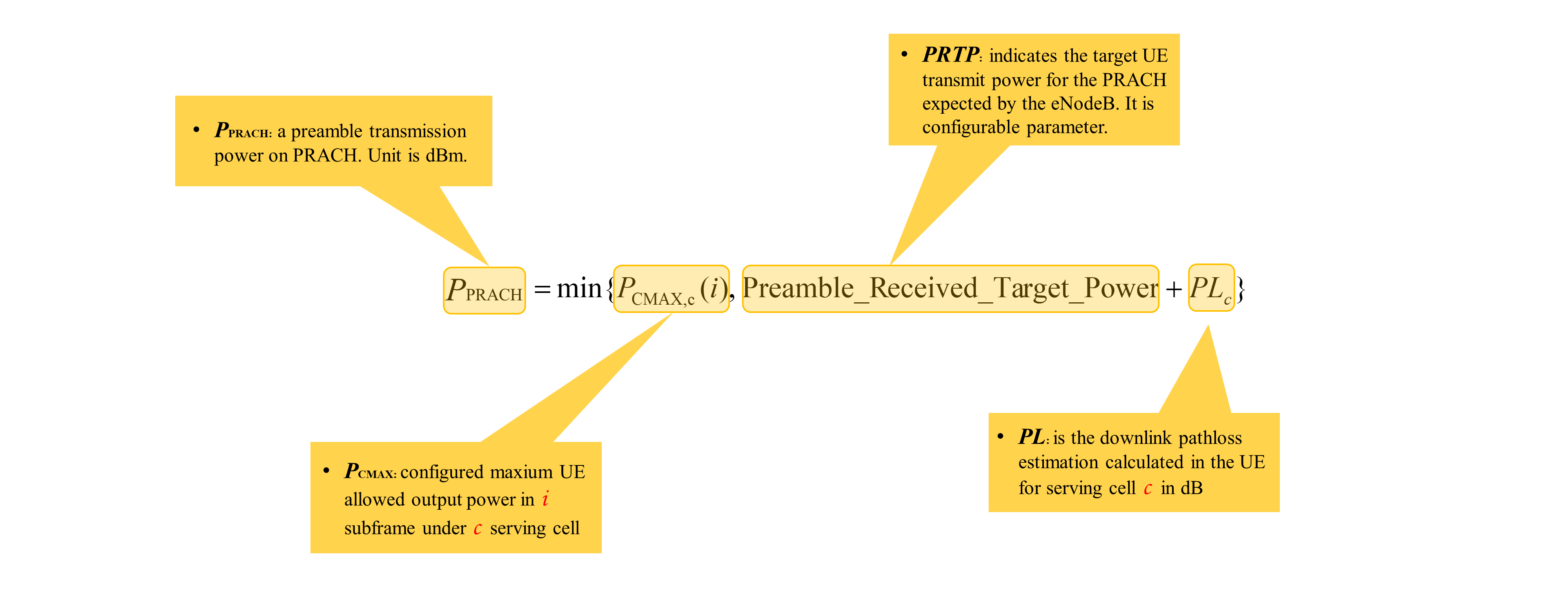
- PPRACH is a preamble transmission power on physical random access channel (PRACH).
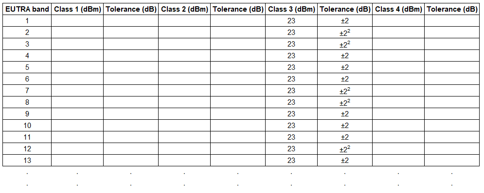
- PCMAX is configured maxium UE allowed output power. The transmitter characteristics are specified at the antenna connector of the UE with a single or multiple transmit antennas. For UE with integral antenna only, a reference antenna with a gain of 0 dBi is assumed. Here an integral antenna means permanent fixed antenna, which may be built-in, designed as an indispensable part of the user equipment. On the following shortened table, we can find UE power class per frequency band.
- Preamble Received Target Power indicates target UE transmit power for the PRACH expected by the eNodeB. Lower value of this parameter will negative impact random access success rate, but higher value will improve it with causing interference on neighboring cells. Proper parameter definition is important (e.g. -104dBm, -106dBm etc.).
- PL is downlink path loss estimation calculated by the UE for the serving cell. This is the related formula:
PLc = referenceSignalPower – higher layer filtered RSRP
where referenceSignalPower is delivered by the network to the UE through SIB2 (see details). Higher layer filtered RSRP means that the measured raw RSRP might not be reported to the network and Layer3 filtering can be applied to the measured result before using for evaluation of reporting criteria or for measurement reporting, by the following formula:
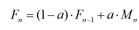
where
Mn is the latest received measurement result from the physical layer;
Fn is the updated filtered measurement result, that is used for evaluation of reporting criteria or for measurement reporting;
Fn-1 is the old filtered measurement result, where F0 is set to M1 when the first measurement result from the physical layer is received; and
a = 1/2(k/4), where k is the filterCoefficient for the corresponding measurement quantity received by the quantityConfig;
Power Control on PUSCH
Physical Uplink Shared Channel is used to transfer user data from the user equipment to the radio network. Like other physical channels when the data is transferred then it needs to be on a certain power for reaching to the destination. High transmit power can cause interference and fast UE battery drain, in opposite way with extreme low power may cause for undelivered data to the network. So, transmit power needs to be controlled.
But how the UE will be aware of the power control mechanism? The answer is serving cell itself. It will instruct the UE about the transmit power through PDCCH. The serving cell sends scheduling information to the UE over PDCCH, then the UE starts to transmit user data on PUSCH. The UE already knows which subframe, MCS and how many resource blocks will be used with the instruction. Now the further step is to calculate transmit power on PUSCH for each subframe (so calculation is based on every 1ms) with using below formula:
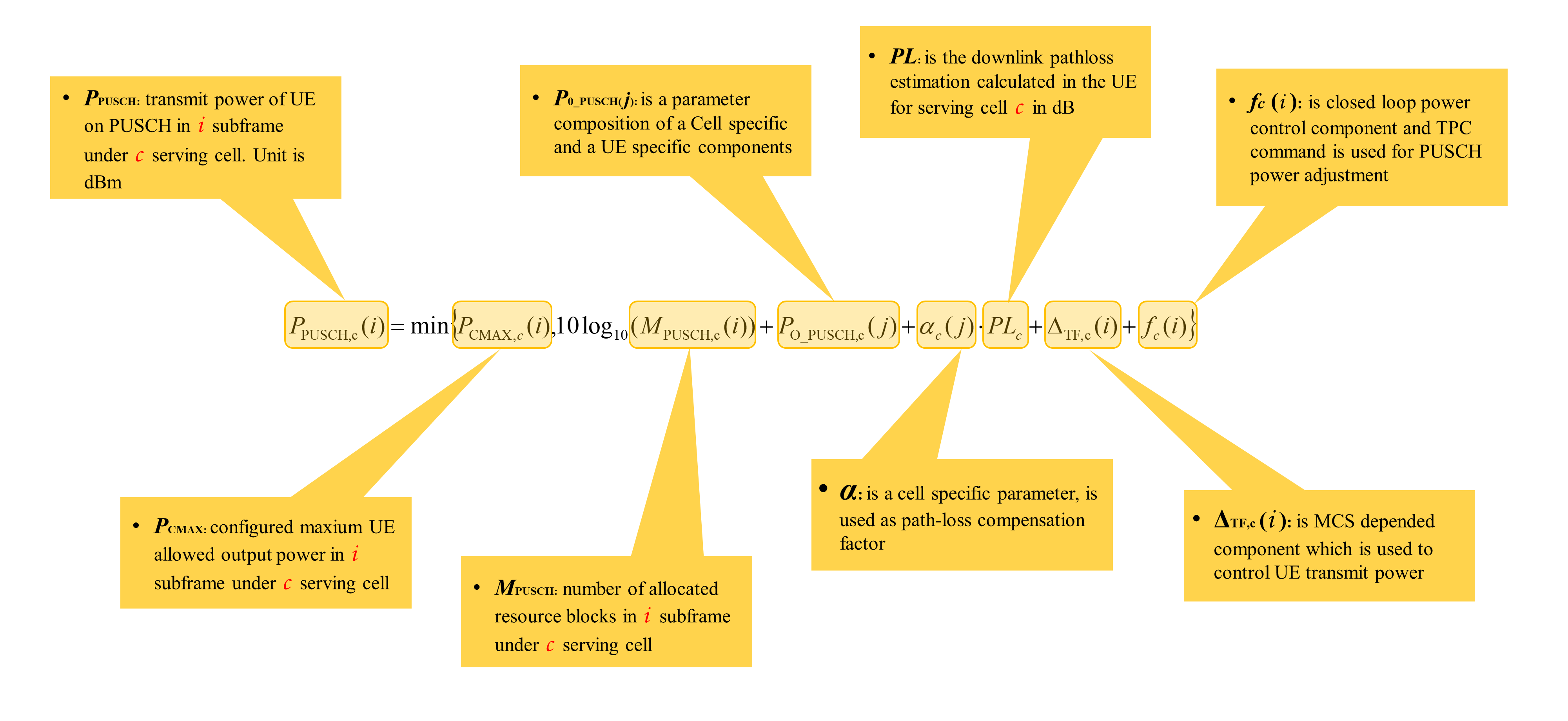
- PPUSCH is transmit power of UE on physical uplink shared channel (PUSCH).
- PCMAX is configured maxium UE allowed output power. For details see above in Power Control on PRACH. Same description is valid for PUSCH too.
- MPUSCH is the bandwidth of the PUSCH resource assignment expressed in number of resource blocks.
- P0_PUSCH is a composition of cell specific and UE specific components configured by higher layers and delivered to the UE to be used in power calculation to transmit on PUSCH, it is also described like eNodeB expected power or eNodeB target received power in some vendor libraries:
P0_PUSCH =P0_NOMINAL_PUSCH + P0_UE_PUSCH
- α (pronunciation is Alpha [ˈælfə]) is used as pathloss compensation factor. It is provided by the serving cell to the UE to be used for PUSCH power calculation in open loop. Following values can be setup {0, 0.4, 0.5, 0.6, 0.7, 0.8, 0.9, 1}.
- PL is downlink path loss estimation calculated by the UE for the serving cell. For details see above in Power Control on PRACH. Same description is valid for PUSCH too.
- ΔTF,c (i) depends on deltaMCS-Enabled parameter whether a UE needs to adjust the transmit power based on the MCS changes or not. It also has own small formula, let’s have a look:
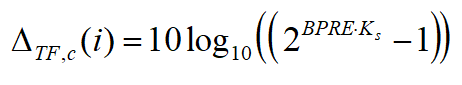
where,
- BPRE is number of information bits per resource element for the scheduled MCS.
- Ks depends on deltaMCS-Enabled parameter switch. If it enabled then Ks is 0, if the switch is disabled then Ks is 1.25. The parameter indication is provided by the serving cell to the UE through RRC Connection Setup message.
Amazing! We have come a long way. It doesn’t look so easy, but we are trying to simplify for you. Let’s take a breath and go to the last piece of the formula which is closed loop part. So far the formula was presenting open loop power control section.
- fc (i ) is closed loop power control component and the current PUSCH power control adjustment state for serving cell which is defined by following formulas (a means cumulative, and b means absolute based on Accumulation-enabled parameter provided by higher layers):
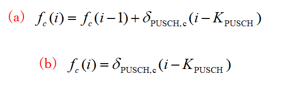
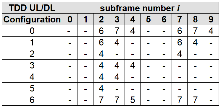
δPUSCH referred to as a TPC command and is signaled on PDCCH with DCI Format0 or DCI Format3/3A on subframe i – KPUSCH for serving cell. For FDD, KPUSCH is 4 subframes (4ms). For TDD, it depends on UL/DL configuration as below:
Above we mentioned TPC command, what does it mean? TPC or with a complete name Transmit Power Control is used in Closed Loop Power Control mechanism to instruct the user equipment to adjust its transmit power (increase or decrease).
Power Control on PUCCH
Physical Uplink Control Channel (PUCCH) is used to carry uplink control information from the UE to the radio network. The conveyed message might be formatted per information type, number of bits. And this type of formations is called PUCCH Formats. Here are some examples such as PUCCH Format1, PUCCH Format1a, PUCCH Format2 and others. The carried information range is large, here we can see just few of them: scheduling request, acknowledgement responses or retransmission requests, channel quality index.
As other physical uplink channels, there should also be some specified standards on PUCCH to control transmission power. Here are we have it:
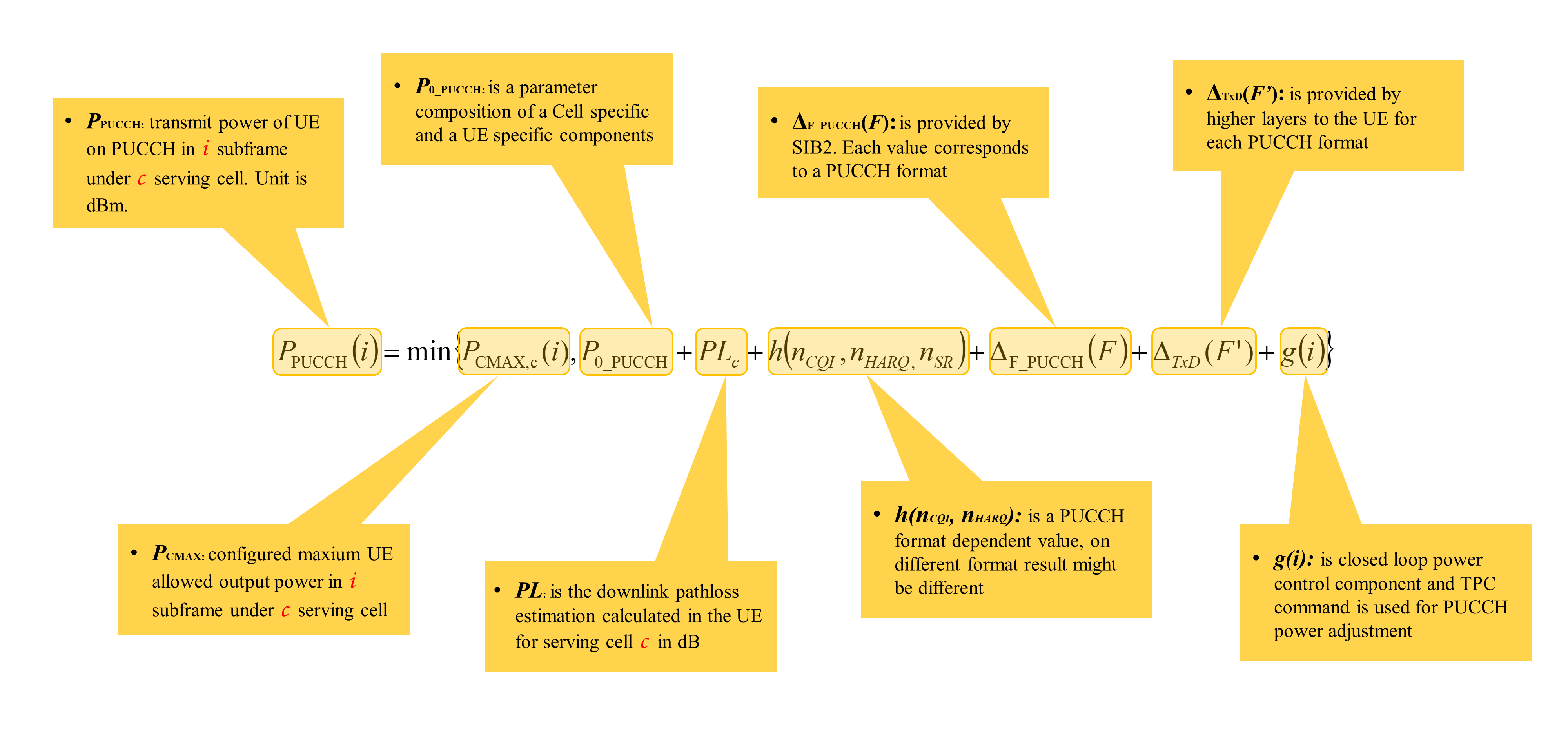
- PPUCCH is transmit power of UE on physical uplink control channel (PUCCH).
- PCMAX is configured maxium UE allowed output power. For details see above in Power Control on PRACH. Same description is valid for PUCCH too.
- P0_PUCCH is a composition of cell specific and UE specific components configured by higher layers and delivered to the UE to be used in power calculation to transmit on PUCCH.
- PL is downlink path loss estimation calculated by the UE for the serving cell. For details see above in Power Control on PRACH. Same description is valid for PUCCH too.
- h(nCQI, nHARQ) is a PUCCH format dependent value, in different PUCCH Format the result might be different.
- nCQI: corresponds to the number of information bits for the channel quality information
- nHARQ: is the number of HARQ-ACK bits sent in subframe
- ΔF_PUCCH(F ) each value of this parameter corresponds to a PUCCH Format and impacts on PUCCH transmit power. It is delta value and the unit is dB. For instance, ΔF_PUCCH for PUCCH Format1 might be set as -2dB, 0dB or 2dB.
- ΔTxD(F’): if the UE is configured by higher layers to transmit PUCCH on two antenna ports, the value of this parameter is provided by higher layers for each PUCCH format; otherwise the value is 0.
- g(i) is closed loop power control component and the current PUCCH power control adjustment state. It also has small formula, let’s skim on it:
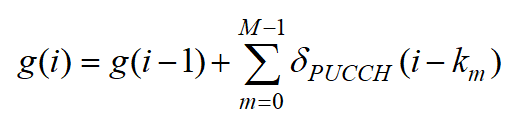
- For FDD, M=1 and k0 = 4
- For TDD, values of M and km depends on UL/DL configuration.
- δPUCCH referred to as a TPC command and is signaled on PDCCH with DCI format 1A/1B/1D/1/2A/2/2B/2C/2D
Power Control on SRS
Sounding Reference Signal (SRS) is a kind of transmitted signal from UE to the serving cell on the last symbol of the subframe of SC-FDMA. If the entire uplink bandwidth could be used all the time, then we would not need such kind of reference signal. But it cannot be, so we would need to use it. Then what is the purpose of this this? The purpose is to help the eNodeB to estimate channel quality of uplink path at different frequencies.
If we are talking about transmission between the UE and eNodeB then it means, there is a power usage and we need to control it not make side effects.
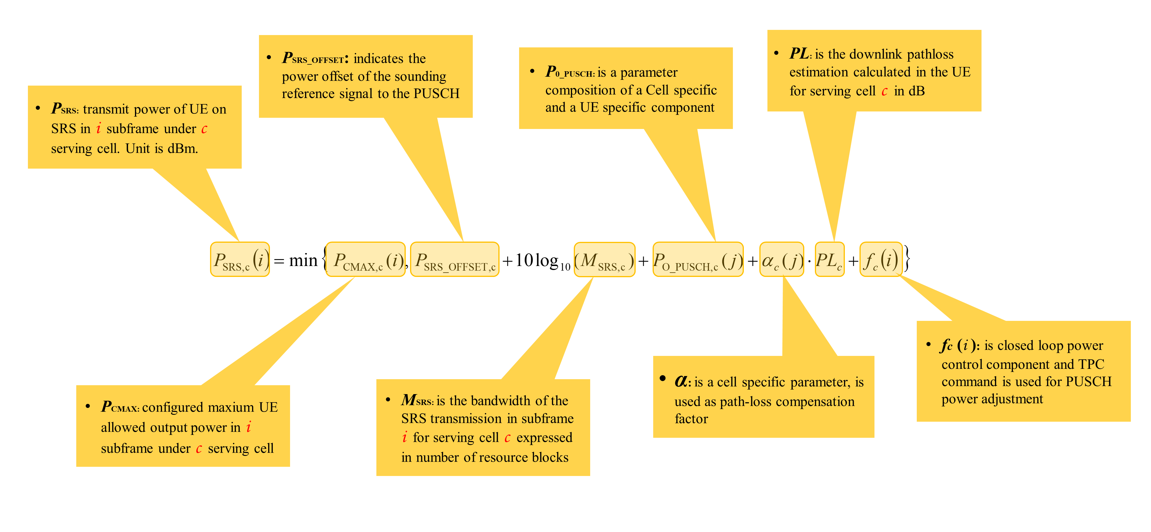
- PSRS is transmit power of UE on sounding reference signal (SRS).
- PCMAX is configured maxium UE allowed output power. For details see above in Power Control on PRACH. Same description is valid for SRS too.
- PSRS_OFFSET(m), basically SRS follows similar PUSCH power control calculation method. PSRS_OFFSET indicates the power offset of the sounding reference signal to the PUSCH. The unit is dB, and configurable (e.g. -4.5,-3,-1.5,0,1.5,3 depends on vendor).
- MSRS is the bandwidth of the SRS transmission expressed in number of resource blocks
- Following three parameters are same with PUSCH power control parameters, you can find details above in PUSCH clause: P0_PUSCH ,α, PL and fc (i )
During Handover , when source cell send RRC reconfiguraton message it does not send Target cell RS powwer. Then how UE calculate path loss for deciding RACH preamble power ? Does it read SIB 2 after receiving HO Command ?