Open RAN with Bullets – Part 2

Even though I have already described high level of O-RAN defined Open RAN architecture in the previous post, now I want to give a bit more details about the architecture options including bundling RAN domain elements in terms of O1 READ MORE

Open RAN with Bullets – Part 1

At current era, all fields of telecommunication are moving forward much faster than comparing previous decades. Even though most of the MNOs have not deployed stand-alone 5G Core network yet, 6G becomes to be appear in the discussion platforms. One READ MORE

LTE UL Power Control in illustrations

The UE will choose minimum power value from the calculation result to transmit user data on PUSCH. The formula consists of three sections: maximum allowed power of UE, open loop components and closed loop component. Here i means subframe, c presents serving cell. (1) Output power on PUSCH (2) Configured maximum allowed UE power (3) Number of resource blocks assigned for PUSCH (4) eNodeB expected power from the UE (5) Pathloss compensation factor (6) Downlink pathloss estimation by the UE (7) Parameter to adjust power based on MCS change (8) Here closed loop power control is used based on TPC commands by the serving cell to the UE. TPC means Transmit Power Control, used for adjustment of transmit power

LTE Regular MIMO in illustrations

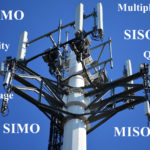
LTE MIMO Transmission can work in two different schemes: SU-MIMO stands for Single User MIMO, MU-MIMO stands for Multi-User MIMO. In first scenario multiple data streams are transmitted to a single user terminal on a given time-frequency resource within a cell. For the second scenario, data streams are spatially multiplexed to multiple user terminals in the same time-frequency resource. In the 3GPP Release 12, up to eight data streams for SU-MIMO and up to four for MU-MIMO are supported. Key advantage of SU-MIMO is interference reduction, for MU-MIMO the advantage is multiplexing gain. In the illustration sample only DL direction was described (just to have an idea), similar is also applicable for UL with some limitation.

LTE DRX in illustrations

DRX is used by user equipment to switch OFF and ON its transceiver (transmission & reception). It is called “Sleeping mode” when the UE switches OFF its transceiver, when it is ON then it is called “Active mode”.